09.12.2019
V. M. Gorbanenko", G. A. Farnasov*, and A. B. Lisafin"a) Technokeramika LLC, village Verhovie, Kaluga region, 249037, Russia
b) National Research University of Science and Technology MISiS, Leninskii pr. 4, Moscow, 119049 Russia
e-mail: a.lisafin@technokeramika.ru
Received January 26, 2015
Abstract—The energy working regimes of a superpower high-frequency induction (HFI) plasmatron with a high-frequency (HF) generator are studied. The HFI plasmatron with a power of 1000 kVA and a working frequency of 440 kHz, in which air is used as a plasma-forming gas, can be used for treatment of various oxide powder materials. The energy regimes substantially influence finish products and their costs. Various working regimes of the HFI plasma unit and the following characteristics are studied: the dependence of the vibration power on the anode power, the dependence of the power losses on the anode power at various of plasma-forming gas flow rates, and the coefficients of efficiency of the plasmatron and the HFI-plasma unit at various powers. The effect of the plasma-forming gas flow rate on the bulk temperature is determined.
DOI: 10.1134/S003602951512006X
INTRODUCTION
Modern high-energy technologies of processing materials play an important role in modern world industry. The success of expansion of the technologies is related to the production of materials with unique properties and a high efficiency of these technologies. A high-frequency induction plasma technology is one of the trends in the high-energy technologies of processing materials. The first works on this technology were published in 1961 [1, 2]. One of the methods of producing materials with unique properties is their processing in high-frequency induction plasmas. The method consists in processing of an initial material in a high-temperature plasma of a HFI discharge [3, 4]. The plasma discharge temperature is up to 11000 K for argon plasma and 9000 K for air plasma. The advantages of applying HFI discharge are a low plasma flow rate, a large plasma volume, a high bulk temperature, and the absence of product contamination [5].
EXPERIMENTAL UNIT
Experiments were performed on an HFI plasmatron with the following working parameters: the supply power was 1000 kV A, the vibration circuit frequency was 440 kHz, the plasma-forming gas was air, and the plasma-forming gas flow rate was 150—300 m3/h. The HFI-plasma unit included an HF generator; a plas- matron consisting of a gas former that stabilizes plasma, a quartz discharge chamber, a work-coil, a charging chamber through which a powder is introduced; a reaction chamber in which a material is melted, evaporated, dissociated, and refined; a cyclone in which a processed material is separated into coarse and fine fractions; a bag filter in which the finest processed particles (to 200 nm) are precipitated; a fan that produces a pressure for creating conditions of the fraction separation; and a bunker for discharging a processed material. The scheme of the HFI plasma unit is shown in Fig. 1. The type of plasma-forming gas significantly influences the energy operating characteristics of the plasma unit. The work of the HFI plasma unit using a nitrogen—oxygen mixture containing to 60% oxygen increases the efficiency by 30% as compared to that during the work using air [6]. However, the addition ofvarious gases leads to a significant increase in the cost of the technological process. This is the reason why the use of air as a plasma-forming gas is economically reasonable.
To qualitatively control the technological process of treating powder materials in HFI plasma, we should analyze the heat regime of operating the HFI plasmatron and the HF generator, determine the power supplied to plasma, estimate the losses in the unit elements, and find the correlation between changes in the electrical parameters and the useful power and the losses.
The HFI plasma unit under consideration has a discharge quartz chamber 140 mm in diameter and 500 mm in height, a work-coil 180 mm in diameter and 330 mm in height, and a gas former that feeds a tangentially swirling plasma-forming gas.
As a result, plasma acquires additional stabilization. This principle is widely used [4].
The HF generator operates as a self-excited oscillator on the base of two 500-kW triode lamps.
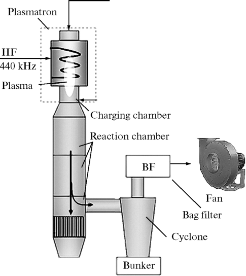
Fig. 1. Scheme of the HFI plasma unit for the dissociation of zircon in air plasma.
The powerful triode lamps, the feedback coil, and the vibration circuit are cooled by deionized water to remove excess heat. The measurements of the water flow rate and temperature were performed using a Metran-305 eddy-acoustic flow meter.
TECHNIQUE OF RECORDING ENERGY REGIMES
The operation of the HFI plasma unit is determined by its efficiency, i.e., by the ratio of the power generated in the discharge to the power consumed by the power supply. The heat losses are traditionally determined using the calorimetric method based on the measurement of temperature and the flow rates of cooling water at the generator lamps, the feedback coil, the capacitor battery, the current leads, and the elements and structural parts of the HFI plasmatron.
The anode power (in kW) is determined from the readings of electrical instruments using the formula
Pa = Ua∙Ia
where Ua is the voltage of the anode supply, kV; Ia is the anode current, A.
The power loss at the HFI unit elements (kW) is
ΔP = 1.163∙Gw∙ΔT,
where Gw is the cooling water flow rate, m3/h; ΔT is the increment of the cooling water temperature, °C; and 1.163 is the coefficient of proportionality.
The summary power loss at the generator lamps, the feedback coil, the capacitor battery, the current leads, the work-coil, and the structural parts of the HFI plasmatron is (kW)
![]() = ΔP1 + ΔPfc + ΔРсЬ + ΔРi + ΔPcp,
= ΔP1 + ΔPfc + ΔРсЬ + ΔРi + ΔPcp,
where ΔP1 are the losses at the generator lamp anodes, kW; ΔPfc are the losses in the feedback coil of the HF generator, kW; ΔPcb are the losses in the capacitor battery bands, kW; ΔPi; are the losses in the work-coil, kW; and ΔPcp is the total power loss in the case of the HFI plasmatron because of heating due to the thermal conductivity and radiation in the plasma, kW.
The vibration power of the HF generator is (kW)
Pp=Pa-ΔP1
The power supplied to the plasmatron is (kW)
Pp1 = Pp - (ΔPfc + Pcp).
The power introduced into the plasma discharge is (kW)
Ppd = Pp1 - (ΔPi + ΔPcp). (1)
The efficiency is determined as the ratio of these powers.
The plasmatron efficiency is
ηpi = (Ppd/Pp1)х100%.
The electrical efficiency of the HF generator is
ηpg = (Pp/Pa)∙100%
The efficiency of the HFI-plasma unit is
ηpu = (Ppd/Pa) ∙100%.
In addition to these formulas, it should be taken into account the heat losses at the generator lamp grid, the anode chokes, the grid leaks, the heating of the diodes of the high-frequency rectifier, thyristors in the power controller, also the current-limiting inductance coil standing after the thyristor controller. There are certain problems of calculating these losses. During operation of HFI plasmatrons with a power of 1—3 MW, the summary losses in the above noted elements are 10—30 kW, respectively.
CALCULATION OF THE BULK TEMPERATURE OF THE PLASMA TORCH OF THE HFI PLASMATRON
There are various aims of treating powder materials, such as the spheroidization, the refinement, the production of nanomaterials, and various plasma torch temperatures are required depending on the aim of treatment.
HEAT-POWER WORKING REGIMES OF A HIGH-FREQUENCY. PLASMATRON
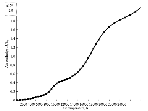
Fig. 2. Temperature dependence of the enthalpy of air.
The bulk temperature of a plasma discharge can be found using the enthalpy method. First, we determine enthalpy Hav,
Hav= Ppd/Qgρg,
where Qg is the plasma-forming gas flow rate, m3/s; Ppd is the plasma discharge power, kW; and pg is the density of the plasma-forming gas, kg/cm3.
Then, we determine the bulk temperature of the plasma torch from the experimental data using the calculated enthalpy (Fig. 2). Ppd was found by Eq. (1).
EXPERIMENTAL RESULTS
The thermal-power regimes of the HFI plasma unit were studied using air as a plasma-forming gas. Note also that the initiation of a plasma discharge and the operation of the HFI plasma unit at the first stage should be performed in an argon atmosphere. To initiate plasma, the grounded metallic tungsten electrode with a sharpened end is lowered to the level of the first—second turn of the work-coil (the position in which the magnetic field is maximal); then, argon is fed into a quartz discharge chamber as the work-coil voltage is 6—7 kV. In this case, electrons are intensely emitted from the tungsten rod surface, ionization achieves a critical value, and an argon plasma is initiated. The argon plasma glows for 30—60 s; during this time, argon is replaced by air. After transition to air, the power is increased to the required level. Operation in air is interesting due to its wider application and a low cost as compared to the case of applying inert or diatomic gases.
The experiments were carried out at various flow rates of a plasma-forming gas (air) at various levels of power. The power was controlled on the low-side of a 0.4/10-kV power transformer at a power of 1000 kVA using a three-phase thyristor controller by varying the thyristor opening angle.
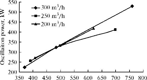
Figure 3 shows the dependence of the vibration power on the anode power of the HF generator. The able, and the difference in the oscillation powers reaches 70 kW at a certain flow rate.
Anode power of HF generator, kW
Fig. 3. Oscillaiton power vs. the anode power at various plasma-forming gas flow rates.
Anode power of HF generator, kW
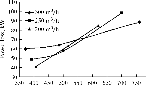
Fig. 4. Power loss vs. the anode power at various plasma- forming gas flow rates.
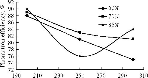
Total plasma-forming gas flow rate, m3/h
Fig. 5. Plasmatron efficiency vs. the plasma-forming gas flow rate at various power levels.
At temperatures higher than 5000 K, air undergoes the process of intense radiation. This peculiarity leads to a decrease in the real power of the plasma discharge. The losses were calculated by summing the losses on the work-coil and the HFI plasmatron body. Figure 4 demonstrates a certain peculiarity of the losses: the losses at a plasma-forming gas flow rate of 200 m3/h are lower by a factor of 1.5 than that at a flow of 300 m3/h. This can be explained by significantly smaller plasmoid volumes at a flow rate of 200 m3/h, which brings about lower losses. As the anode power increases, the picture of the power losses becomes more usual: the losses are maximal at a low plasma- forming gas flow rate.
The plasma-forming gas flow rate influences the efficiency and other operating characteristics of the HFI plasmatron. It is seen that the efficiency of the plasmatron is fairly high (88—90%) at low plasma- forming gas flow rates. This is explained as follows: at low plasma-forming gas flow rates, the losses are minimal with respect to the total power introduced into a discharge. Hence, it can be concluded that it is economically reasonable to work at low plasma-forming gas flow rates and various powers. The only restriction is the physical integrity of the quartz discharge chamber, which cannot work at very low flow rates.
The plasma-forming gas flow rate influences the efficiency ofthe plasmatron (Fig. 5) as in the case of the efficiency of the HFI-plasma unit (Fig. 6). The unit has an efficiency of45—60%, which is a good level [6].
Total plasma-forming gas flow rate, m3/h
Fig. 6. HFI unit efficiency vs. the plasma-forming gas flow rate at various power levels.
dependence is linear: the oscllation power increases with the anode power. The influence of the plasma- forming gas flow rate is insignificant to 500 kW of the anode power; however, above this value, the influence of the plasma-forming gas flow rate becomes notice-
BULK TEMPERATURE OF THE PLASMA DISCHARGE
Various temperature conditions can be provided in the plasma reactor depending on the type of treated material and the quality of a finished product. The main parameter that influences the temperature in the plasma reactor is the plasma-forming gas flow rate. The influence of the average enthalpy on the bulk temperature of the plasma discharge was studied experimentally. The bulk temperature significantly influences the quality of a treated material, but the bulk temperature cannot be very high. A very high temperature can negatively influence the quartz chamber, melt it, and damage it. Figure 7 shows the bulk plasma temperature as a function of the power of a plasma stream for various plasma-forming air flow rates.
The dependence of the bulk temperature on the power of the plasma discharge at various air flow rates is linear: the plasma discharge temperature decreases as the plasma-forming gas flow rate increases at the same plasma discharge power. At a constant plasma discharge power, various processes, such as the sphe- roidization and the refinement of powder materials, can be organized at various plasma-forming gas flow
HEAT-POWER WORKING REGIMES OF A HIGH-FREQUENCY ... PLASMATRON
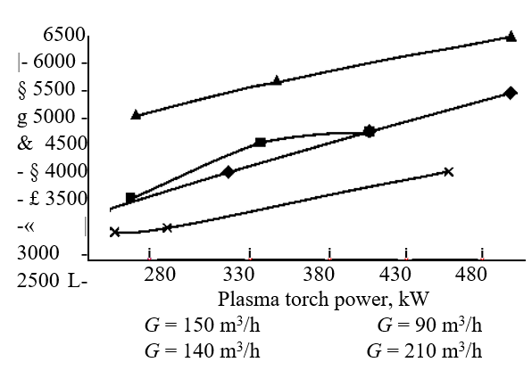
Fig. 7. Bulk temperature vs. the plasma discharge power at various air flow rates.
rates. In the case of industrial treatment of powder materials, the problem of productivity becomes very important. From the standpoint of productivity in the case of spheroidization of powder materials, an advantageous regime is treatment at a low plasma-forming gas flow rate. However, the productivity of treatment of powder materials is significantly dependent on the particle size of a material under treatment [7].
CONCLUSIONS
We studied the thermal-power characteristics of a high-frequency induction plasmatron operating with air. It was found that the plasma-forming gas flow rate significantly influences the oscillation power, the bulk temperature of the plasma torch, and the efficiencies of the plasmatron and the HFI plasma unit. We concluded that it is efficient to perform treatment at low plasma-forming gas flow rates. The bulk temperature of the plasma torch can be controlled as a function of the purpose of treatment of powder materials in HFI plasma.
REFERENCES
1. T. B. Reed, J. Appl. Phys. 32 (5), 821 (1961).
2. T. B. Reed, J. Appl. Phys. 32 (12), 2534 (1961).
3. J. Szepvolgyi and Z. Karoly, “Hollow alumina microspheres prepared by RF thermal plasma,” Powder Technology, No. 132, 211-215 (2003).
4. Pierre L. Fauchais, Joachim V. R. Heberlein, and Maher Boulos, Thermal Spray Fundamentals: From Powder to Part (Springer Science + Business Media, New York, 2014).
5. N. N. Rykalin and L. M. Sororkin, Metallurgical HF Plasmatrons: Electro- and Gasdinamics (Nauka, Moscow, 1987).
6. M. Boulos, “Spheroidization and densification of powders,” in Continuing Education Course on Thermal Plasmas, Held in Conjunction with 16th International Symposium on Plasma Chemistry, Ed. by P. Fauchais (University of Limoges, 2003).
7. Yu. Malakhov, S. Nguenn-Kuok, A. Ageev, and A. Lisafin, “The treatment of oxide powder in RF plasma torch,” in Proceedings of the 12th Asia Pacific Conference on Plasma Science and Technology and 27th Symposium on Plasma Science for Materials (12th APCPTST&26th SPSM) (Adelaide, 2014).
Translated by Yu. Ryzhkov


